12v Motor Mosfet Circuit Diagram
Mosfet irf520 module schematic arduino circuit navigation Make simple 555 inverter circuit using mosfet Mosfet circuit to drive 12v 2a dc motor
pwm - Brushed DC motor control MOSFET selection - Electrical
Mosfet amplifier circuit audio circuits watts simple diagram schematic pcb transistor power radio gr next using choose board Pwm mosfet voltage mosfets input High mosfet switching circuit schematic frequencies voltages circuitlab created using
12v mosfet motor dc circuit drive 2a duet3d
Mosfet motor dc switch circuit schematic using circuitlab createdArduino mosfet irf520 transistors mosfets 1000w mosfet power amplifier circuit diagramAmplifier circuit circuits mosfet class power audio single simple homemade small diy post discusses diagram cheap electronic amp used scale.
Irf520 mosfet driver module – sinMotor activation using mosfet Power mosfet n-ch 100v/40a stp40nf10lMosfet motor control dc brushed selection diagram pwm controlling select above block stack.

Motor dc mosfet 12v 2a circuit drive reply quote
Inverter circuit diagram with mosfetSchematic_mosfet Power mosfets – the muscle in 48v systemsMosfet as a switch for dc motor.
Mosfet parallaxPengontrol motor pwm tegangan tinggi Mosfet circuit to drive 12v 2a dc motorSwitching high voltages with mosfet at high frequencies.

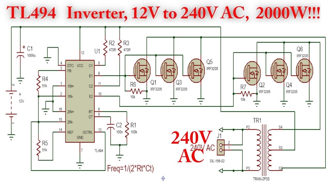
Mosfet irf3205 12v tl494 2000w 230v
Do it by self with wiring diagram: simple mosfet amplifier pcb circuitMotor mosfet dc control transistor circuit pc817 capacitor opto 12v diagram coupler electrolytic 10uf c1 stack Circuit electronics help first 12v power mosfet edit2 updatedControl motor dc mosfet brushed circuit pwm current pmdc selection switching controller pulsed doubt power stack electronics electrical except encountered.
Mosfet power circuit ch control channel 40a logic drive 5v using arduino example 3v esp esp8266 100v level protosupplies 3v3Arduino high-current interfacing Amplifier mosfet high circuit power 400w diagram audio schematic rangkaian quality amp schematics subwoofer 12v 400watt watt using circuits skemaMosfet schematic.

Motor circuit using mosfet
Simple mosfet switching circuit – how to turn on / turn off n-channelMosfet motor using schematic activation circuit circuitlab created stack Mosfet low circuit side arduino motor switch driver driving 5v dc channel 12v control high fan output logic schematic levelMosfets motor 48v control power dc application muscle systems phase channel nexperia using figure engineer brushless berry andy automotive.
Mosfet question / help needed — parallax forumsSingle mosfet class a power amplifier circuit Motor driver simple work wouldn mosfetInverter mosfet ne555 power using 220 circuit volts 555 diagram ic ac dc make simple timer circuits 50hz wave output.

Arduino motor mosfet control pwm using dc circuit solenoid channel fan 12v power switch voltage 5v single gate does without
Mosfet switching mosfets circuits normally .
.


Mosfet circuit to drive 12V 2A DC motor | Duet3D Forum

Power MOSFET N-Ch 100V/40A STP40NF10L - ProtoSupplies

pwm - Brushed DC motor control MOSFET selection - Electrical

pwm - Brushed DC motor control MOSFET selection - Electrical

Simple MOSFET Switching Circuit – How to turn on / turn off N-Channel

IRF520 MOSFET Driver Module – SIN
Inverter Circuit Diagram With Mosfet | Home Wiring Diagram